
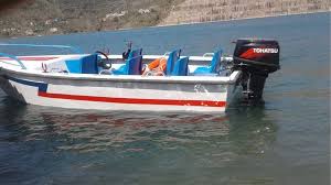
1. Scope:
This specification relates to the detailed requirements for the design, construction, tests & trials,
documentation and warranty of 4.7m RIBs, intended for NDRF.
2. Declaration of Conformity. The boat builder shall build the boat in accordance with the requirements
brought out in this specification and provide a ‘Declaration on Conformity’ with each boat. The declaration
should also contain details of all test methodologies and test results, results of laboratory analyses, factory
tests on the completed hull, as well as report on the water trials of completed boats. Boat builder shall also
submit compliance matrix indicating Para-wise compliance of this specification along with technical bid.
3. Principal Particulars.
Sl Particular Specified Value/Range
a) Length Extreme : 4.70 + 0.05 m
Including appendages
due to OBM & collar
b) Beam extreme including collar : 2.1 + 0.03 m
c) Hull beam overall
(excluding collar) :
:
1.56 + 0.02 m
0.35 m for hull & 0.45 m at
OBM
d) Maximum Draught
including appendages
e) Displacement : Not more than 550 Kgs with all
equipment, accessories
f) Max Speed : 12-15 Knots in Light Load Condition. Light load
condition refers to boat with all fittings, complete
fuel and 03 men crew
g) Economical speed : 6-8 knots under full load
Under full load Condition
Condition
h) Endurance : Not less than 8 hrs. at economical speed and at
full load condition
i) Fuel oil capacity : To meet specified endurance
With 25 % reserve
j) Reserve of buoyancy : Unsinkable even when filled with water with
min 10% reserve of buoyancy
k) Operating sea state : Operating -2, Survival - 3
l) Carrying capacity : 09 including crew
m) Engine Outboard Motor 40 HP 4 Stroke either from
“M/s Yamaha” or
“M/s Mariner” or
“M/s Mercury” or
Any reputed Brand having service support set-up
in India
4. Hull Design:
The hull form offered should be a proven one which can achieve the specified parameters and meeting the above
mentioned dimensions. Details of the hull form offered and authenticity of the design shall be provided along
with the technical bid. Acceptance of such proposal is completely up to the discretion of DG, NDRF. In this
regard, following documents are to be submitted along with T-bid to authenticate that the offered design is proven
one:-
(a) Model test reports/ Evaluation trials by Classification Society to which boat with same hull form has been
supplied in the past.
(b) General Arrangement Drawing.
5. The hull of the 4.7m RIB shall be of the planning type, constructed of Glass Reinforced Plastic (GRP)/FRP
with moulded longitudinal girders supporting fuel tanks and stiffened transom supporting the OBM. The hull
form should be such that the boat meets sufficient stability, maneuverability and sea keeping characteristics. With
respect to stability, buoyancy and strength, the boat should meet all the requirements stipulated in IRS Class rules
6. The freeboard of the RIB with buoyant collar should not be less than 300mm measured from the upper surface
of the buoyant tubes and not less than 250mm at the lowest part of the transom at fully loaded conditions.
7. Class Notation and Approval
The boat shall be designed and constructed as per the latest rules and regulations of High Speed, Light Craft in
GRP composite construction promulgated by Indian Register of Shipping (IRS), Classification Society. The class
approval shall cover the following:-
(a) Hull Design covering stability, maneuvering and sea keeping aspects
(b) Structure, Structural Strength and Construction aspects
(c) Machinery, equipment and associated system arrangements
(d) Electrical system arrangement
(e) Drawings and documents
(f) Boat Trials
8. Boat yard under survey of Classification Society. The construction of boat shall be undertaken in a boat
yard assessed and approved by IRS for construction of GRP powered boats and crafts. In this regard, a valid yard
certification issued by classification society(IRS) for the Boat building Yard is to be submitted along with the
technical bid, which shall bear the following minimal details:-
(a) Location of yard.
184
(b) Last inspection details of the yard.
(c) Validity period of yard certificate.
(d) Capacity and Capability assessment details
(e) Authorization of yard for manufacturing GRP powered boats.
(f) Certification in conformity with classification society Rules and Regulations
9. Inspection, Test & Trials
The boat shall be built under supervision of IRS Class and all the inspections, test and trials are to be carried out
in accordance with class rules and regulations for High speed crafts, Light crafts in GRP / composite construction.
10. Materials
(a)All the materials, workmanship and finish shall be as per international boat building standards and to the
satisfaction of NDRF /IRS. Necessary test reports & specifications of the raw materials/fittings etc. used in the
construction of the boat shall be produced by the Builder.
(b) All the GRP raw materials and hull fittings are to be procured only from classification society approved
manufacturers. Greatest care is to be taken that laminating methods as well as procedures such as bonding and
overlapping conform to practices laid down by classification society
(c) All steel deck fittings shall be of Stainless Steel grade AISI 316. Material test certificates shall be provided
to Inspecting Agency. All forged fittings and the castings shall conform to relevant recognized International/ IS
standards specified in the class rules. The finish of all fittings should be of excellent quality. Stainless Steel (AISI
316) backing plates shall be provided for all deck fittings.
(d) Necessary test reports & specifications of the raw materials/fittings etc used in the construction of the boat
shall be approved by Classification society.
(e) The names and addresses of the firms from whom it is proposed to order/subcontract for various
material/fittings are to be made available to the Inspecting Authority/NDRF and Inspecting Agency, during
inspection. Complete details of the source of each fittings including contact details shall be indicated in Boat
Manual.
11 Mould and Hull Construction
(a) The Builder is to keep in mind continuously the fact that, economy of weight and space is of utmost
importance. An actual and accurate weight record of hull structure, fittings, machinery, equipment, accessories
etc shall be forwarded to NDRF/ Class Society along with detail weight, stability and trim calculations through
Inspecting agency after verification.
(b)The lines-plan and off-set tables extracted from the proven/ offered hull design are to be faired to full scale in
mould loft or using suitable Ship Design software. The faired offsets shall be used for the manufacture of plug
after approval from classification society and plug inspection to be witnessed by IRS
12 Basic GRP Laminate, Tests
Hull and other structural members of the boat shall be manufactured as per the Structural Drawings and Lay-Up
Scheme approved by IRS Classification Society. Glass reinforcement shall be low alkali E type glass and the resin
shall be of unsaturated isopthalic polyester type and shall meet the test requirements as mentioned in latestISO/
BS/ equivalent specifications specified in the relevant class rules. The sample laminate drawn from the hull shall
be tested at a Classification Society/NABL accredited laboratory to relevant standards in presence of Class
surveyor.
13 Inflatable Collar
(a) Inflatable collar of 450 to 500 mm in diameter made of Hypalon (outer layers) and neoprene fabric (inner
layers) composite with1500 GSM and 1670 D-Tex as per ISO 15732, IRS type approved is to be provided. The
inflatable collar shall be subdivided into five in number separate airtight compartments. Each of these
compartments shall be individually inflatable /deflatable, and fitted with air filling and relief valve. The five
compartments of the collar are to be formed by six stern facing conical diaphragms, bonded to the inner surface
of the collar skin. The four internal diaphragms shall be moulded to a minimum of 25mm diameter ends
185
whereas two end diaphragms at the stern (1 each side) shall be moulded to a minimum of 75 mm diameter ends.
End cones are to be suitably stiffened to take impact during astern motion. The tube shall be fitted with heavyduty abrasion cladding on the outboard side all around the boat. The Collar should have an additional fendering
layer at locations likely to encounter repeated bashing/rubbing and stepping by personnel and crew.
(b) The collar shall be attached to the hull using Primary and secondary securing arrangement. The primary
arrangement should ensure rigid connection of the inflatable collar to the hull and ensure water tightness between
the collar and hull. However the arrangement should be such that the collar can be disconnected when required
for necessary repairs. Secondary arrangement of securing collar to the boat should be of suitable number of
polyester webbing reinforced straps on to the hull. The securing arrangement should be approved by the
Classification Society as per the class requirements.
(c) The collar shall serve the dual purpose of providing necessary soft fendering action against impact/abrasion
and additional buoyancy to the boat. A heavy duty cladding work shall be made all around the collar.
14. Mandatory Fitment on the Collar.
The collar should be suitably fitted out to withstand the wear and tear due to usage. Towards this, the collar shall
be provided with rubbing strake (rub strip/wear strip) of vinyl /urethane, 8 inch wide (203mm) with raised ribs.
These rubbing strips should be doubled, tripled, quadrupled, etc. to fully protect outside surface of collar incritical
wear areas. Life lines should be attached to the collar D-rings, grommet strips, or fabric loops. Anti-skid coating
of black urethane with anti-slip features should be provided at essential areas.
15. Additional Hull Fittings on Inflatable Collar.
A removable 12mm braided black polypropylene rope covering shall be provided all around the collar as standard
fitment additional to life lines. A drogue type closing fairlead (Material: AISI 316) shall be bonded to the bow
section of the collar. Twelve molded handholds shall be bonded to the upper surfaces of the collar. Additionally,
following items/ fittings also shall be fitted on hull/ Bulwark at suitable location:-
a. 2 Paddle blade pockets.
b. 1 Sea anchor bucket
c. 2 Paddle handle pockets
d. 1 Drogue type fair lead
e. 2 Rope stowage pockets
f. 2 Fairleads near transom (stbd& port)
g. 1 Bow ring
h. 2 Oar locks (each side)
i. OBS of Collar:
(i) Inflation/ Deflation Values - 05 Nos
(ii) Pressure gauge - 01 No
(iii) Election Inflation pump - 01 No
(iv) Inflation Foot Pump (Reputed make) - 02 Nos
Patching material with adhesive- to repair
Damage/leak in buoyancy
16. Retro-Reflecting Tapes.
White retro reflecting tapes of 10x40cm size shall be pasted on top of collar at bow area, mid-section and aft
section on both port &stbd side.
17. Command Console
(a) A watertight control console for the operation of coxswain shall be mounted on the centre line. All OBM
controls, navigation and common instruments shall be mounted on the console. Battery stowage and electrical
distribution panels shall be housed under the console, access being by side mounted panels.
186
(b) The construction and fitment of console should comply with latest and relevant IP/ IEC standards as specified
in the class rules. All electrical installations, instrumentations and batteries shall be housed inside the console as
per marine standards. The coxswain shall operate the boat from a seated position. The field of vision from the
main helm position shall conform to the requirements of ISO 11591.
(c) A locker space shall be provided under the console with weatherproof inspection hatches for access to the
batteries and for general stowage of foot operated air pump, loose gear etc.
(d) A navigational compass of reputed make shall be fitted on top of the console in a suitable position for the
coxswain use.
18. Deck
(a) The deck shall be of integral closed hull-deck assembly constructed as per classification society rules with
PVC/PUF foam encapsulated FRP construction. A heavy duty washable Anti-Skid Mat of marine standard be
fastened/ pasted on top of deck floor. An ‘Engine well/ Bilge Sump’ shall be made below the OBM mount.
Additionally, a watertight ‘Battery Compartment’ shall be made beneath deck, if batteries cannot be housed
inside command console.
19. Transom
The transom shall be constructed as integral closed hull-deck-transom assembly with OBM mount. Transom
attachment to the boat shall be designed to withstand, the maximum stresses arising from the output power and
torque of the OBM specified by the manufacturer and the weight of such OBM in sea states upto 5. The height of
the transom should be adequate so as to prevent ingress of water from stern during astern motion.
20. Painting
External surfaces of the boat shall not be painted but the gel coat shall be pigmented with reddish orange highly
visible color
All GRP surfaces inside the hull shall be coated with a layer of tissue mat and coated with gel coat pigmented to
orange.
21. Equipment & Fittings
(a) The boat shall be supplied with Standard Equipment and Fittings as per listing given down below and other
additional equipment/fittings mentioned in this specification. All equipment/fittings shall be of reputed make
designed for marine use.
22 Anchor. A CQR anchor weighing 18 lbs shall be stowed on the foredeck. The anchor shall be connected to a
27m of 12 mm dia Nylon rope, stowed on special hinged horns.
23 Bollards and Fairleads. A drogue type closing fairlead shall be bonded to the bow section of the collar.
Appropriate sized bollards made of Stainless Steel AISI 316 shall be fitted to the centre of the forward deck (one
no.) and at the stern (Two nos.). One pair of appropriate sized fairleads made of Stainless Steel AISI 316 shall be
secured to the transom, one to either side of the OBM transom housing.
24 Seating. The helmsman seat shall be for three persons and padded, raised back pillion type. The seating
arrangement with suitable foot holding straps should be provided for balance 06 more persons onboard.
25 Grab rails and Foot straps. Every seat position shall be provided with suitably located handholds
and foot straps. A stainless steel grab rail shall be positioned along fore and aft centerline of the crew seating,
further two grab rails shall be mounted on the console, at forward and at sides.
26. Mast and Navigation Lights. A mast–head light and a combined sidelights for Port and starboard of relevant
IP standards shall be mounted on a Goal Post Mast (SS 316) fitted at an appropriate location. A stern light shall
be fitted as far aft as possible.
27 Life Saving/Rescue. The following lifesaving equipment shall be provided (All stowed in a wooden
box, secured to Deck at suitable position):-
One throwing quoits, complete with buoyant line.
One first aid kit.
28. A manually operated fire extinguisher shall be secured on the side of the helmsman seat.
29. A boat hook shall be provided made of white cedar with Stainless Steel (AISI 316) end hook.
30. All fittings/ items/equipment mentioned in this specification, whether it is fabricated by means of ‘Yard
Supply’ items, or it is procured/ imported from Classification Society approved manufacturers, they should be
of marine quality and the builder is to provide the details regarding source of procurement and the confirmation
of it meeting marine quality requirement along with technical bid.
31. Cradle. One Cradle of Admiralty pattern shall be supplied with the boat
32. Machinery Requirement
(a) The builder shall be responsible for installation of the main propulsion units in accordance with classification
society rules and regulations of High Speed, Light Craft fitted with outboard engines in GRP composite
construction promulgated by IRS Classification Society and meeting the recommendations of engine OEM.
(b) Engine. The boat shall be powered by a standard outboard motor of 40 HP 4 Stroke “M/s Yamaha” OR “M/s
Mariner” OR “M/s Mercury” make or any reputed Brand having service support set-up in India. The OBMshall
be provided with fresh water flushing arrangement & power trim & tilt arrangement. The following aspects are
mandatory for starting/ stopping of engine:-
a. Starting.
i. Both remote and local manual starting arrangements should be provided.
ii.Where there is only electric start, there must be a dual-redundancy starting system with
cross connection. An electric starting system could provide cross-connection to an
appropriately specified secondary battery. This battery need not be dedicated, but must
remain charged at all times.
iii.An over-ride capability must be present, if the Engine stop cord/ switch is accidentally
operated, resulting in engine shut down at a critical moment, such as in big surf.
b. Stopping. Instrumentation of OBM should include an “Emergency Stop switch’ and
a Deadman Switch’.
Engine OBS: Following Engine OBS to be provided.
1.1 Engine oil filter - 03 Nos
1.2 Fuel Filter - 06 Nos
1.3 Air Filter - 02 Nos
1.4 Fuel line with priming valve and connectors – 01 No
1.5 Propeller - 01 No
1.6 Spark Plug - 03 Nos
1.7 Spark Plug Wrench - 01 No
1.8 Water Pump Repair Kit - One Set
1.9 Water Pump impeller - 01 No
2.0 Gear Oil drawn screw washer - 06 Nos
2.1 Lubrication Oil Drain Plug Washer - 02 Nos
2.2 Fuses of all systems complete - 02 Set
2.3 Throttle and Gear shift cable - 01 Set
2.4 Steering Cable - 01 Set
2.5 Automatic Voltage Regulator (AVR) - 01 No
2.6 Fuel Water Separator - 01 No
188
(c) Fuel System.
The engine shall draw fuel from fixed fuel tank of sufficient capacity to meet the endurance requirements
specified in this specification.
The fuel tank shall be constructed of Stainless Steel (AISI 316) and of the size to meet the specified endurance.
The tank shall be fitted beneath the deck. The tank shall be provided with cover plate for cleaning. A calibrated
dipstick shall also be provided which shall be stowed on top of this tank. Fuel water separator to be provided
between fuel tank and OBM.
(d) Instrument Panel.
Standard instrument panel/ instrumentations of OBM as recommended/ offered by OEM of the OBM shall be
mounted in front of the helmsman. Cable wiring shall be loomed inside the console and fed through ‘under deck
cable ducting’ to the engine.
(e) Steering System. The steering shall be from the helmsman position actuated by rim type wheel mounted
at 450
to the vertical and transmitted by a mechanical MORSE system to OBM Unit at the transom.
Arrangement for direct tiller control should also be provided. Cable wiring and hydraulic system shall be
loomed inside the console and fed through ‘under deck cable ducting’ to the engine.
33. Bilge System. A semi-rotary hand pump of 1000 litres per hour capacity shall be provided in the aft end.
The pump shall be of standard make (ISI) capable of taking suction from the bilge sump aft.
34. Tally Plates. Instruction tallies in English and Hindi engraved on quality melamine plastic laminates
shall be located next to individual items of equipment.
35. Tools. The following standard tools (One set each) shall be provided in addition to special tools
recommended by OEMs for OBM in a suitable portable aluminum tool box.
(a) Open Spanner : 10X12, 13X17, 14X15, 19X22
(b) Socket : 13X12.5, 15X12.5, 17X12.5,
19 X12.5, 22 X12.5, 24 X12.5,
27 X12.5,
(c) T Handle : (One in no.)
(d) Extension for socket : 12.5 X12.5
(e) Screw Driver : A.0 8X5.5X1.25
(f) Feeder gauge : 0.2X0.45
(g) Box spanner : One set.
(h) Torque spanners : One set.
36. Electrical Requirements
(a) The installation of electrical systems and equipment/fittings which is not specified in this specification
shall be in accordance with classification society rules for High speed crafts / Light crafts in GRP / composite
construction.
(b) The equipment shall include switches of sealed type for all main services other than engine starting,
voltmeter, ammeter, indicating lamps as well as HRC fuses of appropriate capacity and meeting IP 66
standards and should comply to IEC publication on marine equipment/ spares or any other equivalent
international standards. The builder should indicate the standard to which the electrical system is installed
and its compliance.
37. Engine Start Control. The engine start shall be controlled by a 2 position (off/ignition) key switch and
a start push-button. Under normal starting conditions the 10 amp circuit breaker shall connect the 12 Volt
Positive supply from the battery to the engine start key switch.
38. Batteries. Suitable number of 12V Sealed Maintenance Free batteries to be provided to cater for total
electrical load for three hours onboard, with 100% redundancy. Provision for charging these batteries by
OBM and through a suitable battery charger from mother ship/shore to be provided. A suitable battery
charging socket of IP66 rating or higher shall be mounted on console for charging the batteries. The
distribution panel shall be located in the helmsman console, with isolation/change over switch facility for
battery charging
39. Search Light. Search light be supplied and fitted on boat with standards as specified in terms of
parameters stipulated in LSA code [Resolution MSC.48(66)] vide Article 5.1.2.2.11. The wattage of search
light being selected shall be in compatible with the standard electrical supply available in the boat.
40. Electric Horn. A marine electric horn of 'type approved' for boats of length less than 5m be supplied
and fitted on console.
41. Lighting. The 12 Volt positive supply shall be connected from the bus bar to the following lighting circuits
as described:
(a) Navigation lights - through a circuit breaker of suitable
rating and switch.
(b) Panel and Compass lights - both supplied through a common
circuit breaker of suitable rating, and
individual switches.
(c) NUC and Special Ops Lights - both supplied through a common
circuit breaker of suitable rating to the
NUC and SO sockets for
temporary lighting.
42. Identification Tallies. Identification tallies in English engraved on quality melamine plastic laminates
shall be fitted adjacent to following:-
a. Principal electrical outlets.
b. Switches at console
c. Instruments at console.
43. All electrical equipment/fittings are to be of class approved/ COTS. Navigational lights to be fitted are
to be IMO / MMD certified / cleared.
44. Lifting Arrangement
(a) The boat shall be fitted with/ suitable four point lifting arrangement. A four-leg polyester
webbing sling to be supplied along with the boat. The sling is to be shackled to these slinging points
by bow screw shackles. The bolts of these shackles shall be moussed to prevent them working loose.
The sling shall have a safe working load of 1.5 tonnes and an in-use life of two years without any
load testing requirement during this period, from the date of supply. The sling is designed to place
the RIB horizontally in the water. The builder should provide load test certificate for the sling set to
twice the Safe Working Load.
45. Strong Points. All Strong points designed and fitted for towing, anchoring, mooring etc. shall be
fastened permanently to its position and tested with reference to ISO 15084, Small craft – Anchoring mooring
and towing, strong points (or relevant standards promulgated by any classification society).
46. Drawing & Documents
Once the order has been placed for the boats, the firm could progress with ordering of long lead items,
equipment, machinery and fittings. But no construction shall commence until the drawings and
documentations are scrutinized and approved by Classification Society IRS for its compliance with class
rules and the requirements of this specification
47. As Fitted Drawings/Documents. On successful completion of all tests/trials and prior to the delivery of
the boat, the builder shall supply all the drawings approved by classification society, and in addition, supply
following instruction and maintenance manuals of all fitted equipment to NDRF/Inspecting
agency/Consignee.
190
One set of technical documents of OBM, its associated accessories and pumps be forwarded to NDRF
prior to the PDI. The technical documents/manuals should include the following:-
i. Technical description.
ii. System Drawings.
iii. Operation Manual
iv. Maintenance and Workshop Manuals
Parts Catalogue. Both hard and soft copy of parts catalogue be provided.
48. Boat hand book. Containing brief description of all features of the boat and its photographs from
various angels. This should cover following in brief:-
a Functions
b Identity
c Speed
d Endurance
e Displacement
f Draught corresponding to displacements
g Principal Dimension
h Environmental limitation
i Manning requirement
j Carrying capacity
k Brief description of lifting arrangement and precautions to be observed
by the user.
l Safety equipment provided
m Fuel and coolants to be used as recommended by OEMs
n List of principle drawings and documents
o Brief operating instructions on OBM
p Parameters of stability
q Collar fitment and Removal Instructions
r Care and maintenance of collar (including sources and technical details of
collar material)
49. Operation manuals of OBM. The operation manuals shall consist of the following :-
a Introduction
b Operating information
(aa) Normal operation and limiting values
(ab) Operation under special conditions
(ac) Break down and emergency repairs
(ad) Fault finding
(ae) Performance & test data
c. Technical Description
(aa) Construction detail
(ab) Setting to work
(ac) List of non-repairable items
(d) Maintenance and Workshop manuals of OBM. This must include following
:-
a. Preventive and corrective maintenance
b. Procedure/Guidelines to carry out maintenance which is to include Top
Overhaul/ Major Overhaul
c. Performance and other fault location
d Weight and dimension for lifting purpose
e Maintenance tree
f Special tools
g Reclamation procedure for worn-out or damaged parts
Alignment procedure
Any special instruction
h Parts catalogue for OBM.
50. Report of Tests and Trials. All tests and trials carried out by the IRS are to be compiled into a book
form and a copy of same is to be forwarded to the consignee along with the boat with a copy to NDRF.
51. Tests & Trials
A programme of tests and trials as per Class requirements shall be prepared by the Builder. On completion
of each test and trials detailed reports of the tests and trials carried out are to be forwarded to NDRF duly
endorsed by IRS.
On satisfactory completion of the trials, detailed reports in bound copy shall be forwarded by the Builder to
NDRF for every boat separately. Reports shall also include proposals (if any) to improve the performance of
the boat and if these are minor in nature, the Builder shall carryout such modifications at no extra cost.
Authority for re-ordering trials rests with NDRF if satisfactory results are not achieved and the Builder
shall comply with such directives as and when issued within the contracted delivery period.
52. Training
Boat builder should provide free training on operation and first line / second line maintenance to two
officers and six other ranks. Training shall be conducted with infrastructure by OEMs at the location of
consignee specified by NDRF and should be in English Language. Training may be conducted in
conjunction with boat construction and acceptance trials.
53. Warranty
The boat(s) supplied against this specification be deemed to bear a warranty of the boat builder against
defective material, equipment, machinery, workmanship and performance for a period of 24 months from
the date of receipt of boat by the consignee. If during this period the boat, its material, machinery or
equipment supplied are found by the consignee or ultimate consignee to be defective/substandard, the
same shall be replaced/repaired within a period of 15 days from reporting, free of charges at site
(anywhere in India) by the boat builder. In case the reported warrantee defect is not rectified within 15
days, the total delay caused in rectification will be added to the Warrantee period.
54. Product Support
All the equipment and machinery fitted onboard should have indigenous product supportability by the
OEM or its authorized reps for a minimum period of 12 years from the date of supply of the boat. The
certificate of the same from the OEM shall be attached along with the technical bid.
STANDARD EQUIPMENT AND FITTINGS
Qty Item
1 Bollard (fwd)
2 Mooring cleats (aft)
2 Stern fairlead (fitted on transom)
2 Mooring warps
1 Calibrated fuel tank dipstick
1 Fuel filler cap with key
1 Bow Fairlead (fitted on collar)
2 Stern fairlead (fitted on collar)
3 Negro Head Bollard (positioned corresponding to fair leads)
4 Navigation lights and white streaming light (Aqua signal
series 25)
1 Set Lifting eye plates
1 Goal Post Mast Support Frame
192
1 Sea Anchor, Stowage bucket, deck eye and line
1 Towing eye ‘U’ bolt through stem
2 Paddles made of white cedar with stowage
2 Boat Hooks with stowage
2 Box stowage
1 set Anchor chocks (to suit supplied 18 lbs CQR anchor)
1 set Canvas covering on all handrails
1 set Point Lifting Slings (Webbing)
2 Mooring rope stowage (collar mounted)
1 Semi Rotary hand pump of capacity 1000 ltrs/hr.
1 Instrument panel spray cover – PVC/Celluloid
1 Battery charger
2 Watertight plug and socket (NUC) and special Ops light
2 Identification plates
1 set Tallies
1 Collar repair kit
1 Anchor CQR type 18 lbs with stowage
27 m Anchor cable 12 mm with stowage
2 One of 1.4 Kg BCF and one of CO2 Fire extinguisher with
stowage
1 Hand signalling lamp with stowage
1 Compass with stowage
1 First aid kit with stowage
10 Life jackets with stowage
1 Stowage box for 6 hand flares
1 Portable search light
1 Set Special tools for overhaul of engine/whistle
1 Electric fog horn
1 Effective radar reflector
2 Maintenance free sealed batteries, 12V, 100AH
1 Aldis Lamp
1 set canvas cover for the boat
1 Cradle
1 FRP repair kit
Additional Fittings on Collar as mentioned
Lifesaving/ Rescue kits as mentioned
Tools and Tool Box as mentioned