
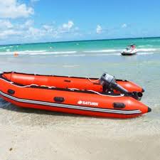
INFLATABLE MOTOR RESCUE BOATS BIG (20 SEATED)
Category: Flood Water Rescue (FWR) Equipment
Color: Red,
Size: ,
204 100. INFLATABLE MOTOR RESCUE BOATS BIG (20 SEATED) SPECIFICATIONS PICTURE OF EQUIPMENT BOAT ASSAULT UNIVERSAL TYPE (BAUT) : CQAE/1940/1575 O.B.M. 50 HP : CQAE/2010/1615/(a) Univarsel DEFENCE SPECIFICATION FOR BOAT ASSAULT UNIVERSAL TYPE-1A FOREWARD 1. This specification has been prepared by the Controller ate of quality Assurance (Engineering Equipment), Aundh Camp, Pune-411027 on behalf of Director General Quality Assurance, Ministry of Defence, New Delhi. 2. This specification has been prepared to lay down general requirements. This would be used to guide manufacture/quality Assurance/Inspection used for Boat Assault Universal Type 1A. 3. This specification consists of 27 page. 4. This specification shall be used for tender enquiry, procurement , manufacture and quality assurance proposes of the equipment covered in the specification. 5. This specification is restricted document and therefore should not be communicated to anyone who is not authorized to receive it. 6. This specification with accompaniments should be returned to issuing /purchasing authority on completion of tender formalities or completion of supply order. 7. The Controller, CQAE, Aundh Camp, Pune-411027 is the authority holding sealed particulars ( AHSP) and doubt, regarding any statement covered by this specification shall be referred to the AHSP who will clarity the same. In case of any anomaly the AHSP’s decision on technical requirement shall be final and binding on the supplier. Any legal or contractual conation shall be final and binding on the supplier. Any legal or contractual conation shall be referred to the contract placing authority. 8. The quality Assurance Authority for the item covered in this specification is the CONTROLLER, CQAE, PUNE-411027 and quality assurance officer of the area concerned will be the Senior Quality Assurance Officer (SQAO) or Senior Quality Assurance Establishment ( Engineering Equipment’s) located at Mumbai, Kolkata, Chennai, New Delhi or an officer nominated by him. SQAO shall carry out bulk quality assurance of the item. 9. Clause by clause reference of this specification should be confirmed in writing along with tender enquiry documents/quotation otherwise the tender documents are liable to be refected due to incomplete/inadequate details. 10. No deviation for stipulated parameter of specification/drawing will be accepted without the concurrence in writing by AHSP and no request will be entertained directly from sub-contractor, if any. The main contractor shall remain responsible for the quality of the product. 11. The contractor shall extend to the defence QA authority or his authorized representative all reasonable facilities for QA and testing of the equipment including gauges free of cost. In order to ensure that the stores 205 ordered are produced strictly as per this governing specification the QA authority or this dispatch stage at the manufacture’s works at all times during the currency of the contract. If the need is felt he will also have free access to procurement document including books of accounts. In case any sub orders are placed on sub contractors the prior approval of sub contractors by AHSP shall be obtained and copies of sub contract shall be provided to AHSP and the SQAO of the area concerned. All inspection and test facilities shall be provided free of cost for the sub contracted items. 12. Advance or pilot samples, if any stipulated in the contract are required to be submitted to the inspection authority of CQAE Pune-411027 on door delivery free transportation/handling cost within stipulated delivery period for testing and approval before undertaking bulk manufacture of item and bulk manufacture if undertaken by the contractor, prior to approval of advance /pilot sample will be of the risk and cost of the supplier/contractor. The bulk suppliers will be affected strictly as per the approved advance/pilot sample including any improvement /modification suggested during approval of the advance/pilot sample. 13. Stage inspection will be carried out right from raw material stage to dispatch of the stores and such stage inspection shall not be construed as absolving the contractor of his responsibility in carrying out a comprehensive pre-inspection on his own part and stage inspection by defence QA agency i.e. without any prejudice to the right to reject the complete/offered article manufactured from such stage inspected components/sub-assemblies/assemblies, if found not conforming to specified requirements. 14. Any defects as notified during inspection by QA agency shall not be rectified /repaired without prior approval of the defence QA agency. 15. The manufacturer/contractor is required to incorporate latest technology state of the on manufacturing procedures and test methods in turning out the product in meeting the requirements of reliability, serviceability, interchangeability and durability of the product. 16. The warning/safety aspects of the store have to be kept as per standard practice Guidance in manufacture of the store shall be taken from patent or samples, if any available with the defence authorities. 17. Copies of any national or international or any other specifications, instructions or guidelines stipulated in this specification for reference shall be obtained from the publishers of the respective documents. The latest version of these documents shall be applicable. 18. This specification shall be used for the sole purpose of manufacturing and supplying the store to the defence indenter against a specific contract only and not for any other purpose whatsoever. 19. The manufacturer/suppliers are required to provide all necessary technical information to fully identify the item. This information is required for defence codification purposes only and in no way jeopardize the commercial interest of the suppliers. Non-compliance of this requirement by contractor is likely to render his bid for supplying defence equipment being rejected. SCOPE 1. This specification intended to govern the manufacturing, material, quality Assurance identification, preservation and packing of boat Assault Universal type1A. 2. Related Specification, Drawings And Documents 2.1 Specifications: 2.1.1 Indian/British Standards : The following specifications(latest edition) published by bureau of Indian standards/British standard instituts have been made use in preparation of this specification: S. NO. SPECIFICATION NO. TITLE 1. IS:736 Wrought aluminium and aluminium alloy plates for general engineering purposes. 2 IS:737 Wrought aluminium and aluminium alloy sheets and strips for general engineering purposes. 3 IS:740 Wrought aluminium and aluminium alloy rivets for general engineering purposes 4 IS: 844 Screw drivers. 5 IS:919 ISO systems of limits and fits. 6 IS:1278 Filler rods and wires for gas welding 8 IS:1285 Wrought aluminium and aluminium alloy extruded round tube and hollow sections for general engineering purposes 9 IS:1364 Hexagon head bolts, screws and nuts. 10 IS:1365 Slotted countersunk head screws. 11 IS:1366 Slotted cheese head screws. 12 IS:1570 Schedule for wrought steels. 206 13. IS:1572 Electroplated coatings of cadmium on iron and steel 14 IS:1874 Ready mixed paint, universal, zinc chrome priming (synthertic) for light alloys 15 IS:1875 Cardon steel billets, blooms, slabs and bars for general engineering purposes. 16 IS:2016 Plain washers. 17. IS:2062 Steel for general structures purposes. 18. IS: 2074 Ready mixed paint, air driving, redoxide zinc chrome priming. 19. IS:2102 Tolerance for linear and angular almensions with out individual tolerance indication. 20 IS:2507 Cold-rolled steel strips for springs. 21 IS: 2907 Non ferrous rivets 22 IS:4671 Expandable polystyrene for thermal insulation. 23 IS:5192 Natural rubber compounds 24 IS:5666 Etch primer 25 IS;6911 Stainless steel plates sheets and strips 26. IS:7283 Hot rolled bars for production of bright bars and machined parts for engineering application. 27 IS:10607 Ready mixed paint, finishing, general purpose synthetic, SG Shade. 28 BS:970 Wrought steels 2.1.2 Defence specifications: The following defence specifications have been referred to in this specification. S.NO. SPECIFICATION NO. TITLE 1. CQAE/2090/1404 Boat hook, 3.54m 2 IND/ENG/PROV/11 81 Paddle, Timber 3 Ind/ENG/PROV/117 2 Oar,3.05 m 4 IND/GS/13239Lates t) Chains 5 IND/SL/0062(Latest ) Wood preservative 6 JSS 8010-5 Paint RFU Finishing non slip, Deck, brushing, dark admiralty Gray. 02.2 DRAWING: The use of following drawings (latest) is mandatory for manufacture and supply of boat assault universal type1A. s. No. Drawing No. Nomenclature/Description 1. IMGA-00729Sheet 1 of 4 sheets) Schedule of drawings, material and std parts boat assault universal type 1A. 2. IMGA-00729Sheet 1 of 2 sheets Schedule of drawings, material and std parts splash panel for boat assault universal type 1A 3. IMGA-0072(Sheet 2 of 4 sheet) Indoard profile and plan. 4 IMGA-0072(Sheet 3 of 4 sheet) Outboard profile and bottom plans. 5 IMGA-(Sheet 4 to 4 sheet) Line plan. 6 IMSA-0050 Stern transom. 7 IMSA-0051 Bow transom 8 IMSA-0052 Coupling arrangement 9 IMPD-0483 Floor beam seat intermediate 10 IMPD-0484 Floor beam seat att 11 IMPD-0485 Floor beam seat forward. 12. IMPD-0486 Connecting angle short 13 IMPD-0487 Connecting angle long. 14 IMPD-0488 Hat stiffener 207 15 IMPD-0489 Hat stifferetatt 16 IMPD-0490 Bracket indoord femable 17. IMPD-0491 Bracket trackway 18. IMPD-0492 Bracket row lock 19 IMPD-0493 Clamp row lock. 20 IMPD-0494 Clamp chain 21 IMPD-0495 Housing repair Kit 22 IMPD-0496 Box with repair kit 23 IMPD-0497 Foot walk forward 24 IMPD-0498 Foot walk intermediate 25 IMPD-0499 Foot walk aft. 26 IMPD-0501 Closure plate bow end. 27 IMPD-0502 Closure plate intermediate. 28 IMPD-0503 Skid. 29 IMPD-0504 Mid Wale 30 IMPD-0505 Chine 31 IMPD-0506 Side stiffener diagonal 32. IMPD-0507 Side stiffener vertical short 33 IMPD-0508 Hand rail 34 IMPD-0509 Sheet sten 35. IMPD-0510 Inner plates 36 IMPD-0511 Stiffener intermediate 37 Impd-0512 Boundary angle, side 38 IMPD-0513 Boundary angle, bottom 39 IMPD-0514 Doubler plate port outboard. 40 IMPD-0515 Doubler plate port inboard. 41 IMPD-0516 Doubler plate stbd outboard 42. IMPD-0517 Doubler plate stbd inboard. 43 IMPD-0518 Filler block side 44 IMPD-0519 Filler block centre 45 IMPD-0520 Chine end, closure plates 46 IMPD-0521 Outer plate 47 IMPD-0522 Stifffener End. 48 IMPD-524 PINdECK COUPLING 49 IMPD-0525 Link side 50 IMPD-0526 Bracket with pivot on 51 IMPD-0527 Bottom Lock pin, Link side 52 IMPD-0528 Doubler plate side. 53 IMPD-0529 Doubler plate transom 54 IMPD-0547 Splash Panel, Centre 55 IMPD-0548 Splash Panel 56 IMPD-0549 Bracket 57 IMPD-0550 Clamp screw 58 IMPD-0551 Button. 59 IMPD-0552 Clamp screw Handle. 60 IMPD-0553 Clamp splash panel 61 IMGA-0073(Sheet 2 of 2 sheets) Splash panel Assembly. 62 IMPD-0531 Doubler plate port Intermediate. 63 IMPD-0532 Doubler Plate stbd intermediate. 64 IMPD-0533 Anchor Ring Bracket 65 IMPD-0534 AnchorRing 66 IMPD-0500 Closure plate stern end. 67 IMPD-0530 Dolley Rivering. 68 IMPD-0535 Side stifferner, VerticalLong’ ‘A’ 208 69 IMPD-0536 Horizontal stiffener short 70 IMPD-0537 Horizontal stiffener long 71 IMPD-0538 Side stiffener, Vertical long,’B’ 72 IMPD-0539 Side Stifener, Vertical long,’C’ 73 IMPD-0523 Deck coupling 74 IMPD-0540 Cap, Detachable, Nylong for pin pivot 75 IMPD-0573 Buoyancy Material ( Thermocale). 76 IMPD-1497 Hook Boat. 77 IMPD-0340 Bailer FBE 78 IMPD-0542 Row Lock with Chain 79 IMPD-0543 Spike Braiding 80 IMPD-1835 Paddle, timber 81 IMPD-1824 Oar,3.048m 82&83 ISK-0790 & 0792 Pop Rivet, Blind, Aluminium alloy 84 GGA-0056 Gauge drawing-Link side 85 GGA-0057 Drilling jig of deck coupling 86 GGA-0058 Drilling jig of DECK COUPLING. 87 Gsa-0085 Sub Assy Jig Body 88 GSA-0086 Jig welding assy 89 GSA-0087 Sub Assy Jig Unit. 90& 124 GPD-0493 to GPD0527 Detailed drawings of Jigs. NOTES: i. Indian /British standard specifications are obtainable from bureau of Indian standard, Mank Bhawa, 9 Hahadur shah Zafar Marg, New Delhi -02 or from their regionnal offices. These standards are mandatory for production and supply of this store. ii. Copies of the drawings listed out at clause 02.2 and defence specifications listed out at Srl No. 1 , 2 & 3 to clause 02.1.2 are obtainable from the controller,CQAE, Aundh Camp, Pune411027 on payment of hire charges ( non refundable). Defence specificaions listed ut at srl No. 4, 5,& 6 TO CLAUSE 02.1.2 ARE OBTAINABLE FROM THE CONTROLLER, cqa(gs). Kanpur, Controller CQA (Materials), Kanpur and Directorate of standardizaton. New Delhi respectively on payment of hire charges (non refundable). iii. Reference to this specification in relation to any Indian standard/any other specification/drawing in any tender enquiry/supply orders/acceptance of tenders means the paper particulars (above documents) shall be latest one and the current edition at the date of such tender/contract/AT/SO. TECHNICAL REQUIREMENT/END USE 3.1 General Description. 3.1.1 Boat assault universal type (BAUT) 1A is used for ferrying of 16 fully armed personnel and 2 operating crew for assault or able to transport a cargoof 1400 Kg at a free board of 310mm. It is also used for evacuation of causalities. Heavier loads up to 2300 kg can be transported with a free board of 200 mm provided the condition of water current permits. Two boats can be coupled together stern to stem thereby forming a single boat of double carrying capacity. 3.1.2. The boat is made out aluminium alloy sheets with reveted construction and is nearly flat bottomed with trapezoidal hull wich ends in a slightly uptumed bow structural rigidity to the boat is given by providing corrugations to the bottom sheet stiffeners to the side speets and a floor seat beams which are tilled with buoyancy material. The floor seat beams, apart from actingseats for the Personnel, provides a reserve buoyancy of over 100 kg and render the boat practically unsinkable. Brackets assembly to the boat. Housing for the storage of repair kit is provided in the third floor seat beam from bow side. 3.1.3. The boat can be propelled manually with 8 oars/paddles or by an OBM of 34kw rating (supply of OBM is not included in the scope of this specification which can be fitted either at bow end or at stem end. 209 3.1.4 TECHNICAL DATA 03.3.1 Length : 5200 mm 03.03.2 Width : 2100 mm 03.3.3 Depth : 510 mm 03.3.4 Weight ( less OBM) : 200 Kg ( Approx) S. No. Typical Load Free Board Draught Speed 1. Single boat unladen-only with OBM and operating creq of 2. 490 mm 20 mm 10m/Sec 2 Single boat laden with 16 fully equipped men or a unifrmly distributed load of 14oo Kg & crew of 2. 230 mm(min) 270 mm(av) 280 mm 240mm 3.4m/sec 3 2 Coupled boats laden with 106 mm RCL gun mounted willys jeep OBM operators and gun crew. 260 mm(min) 350mm(av) 250mm 160mm 2.5m/sec 4 2 Coupled boat laden with 200kg (uniformly distributed load of 100 kg in each boat) & OBM operators. 290 mm(min) 320 mm(av) 220 mm 190 mm 4.25m/sec 5 2 Coupled boats with crew when empty 5m/sec 03.2 COMPONENT DESCTRIPTION 03.2.1 Splash Panel Set:The splash panel Set is fittedto the bowof the boat when heavily loaded boats are required to be operated in heavy water currents to prevent water splashing into the boat. It is made out of aluminium alloy sheets and is fitted with rubber pads. The complete set consists of three panels as given beloow: 03.2.1.1 Splash Panel Centre: It is made of aluminium alloy sheets and is trapezoidal in shape. It is 2148 mm length, 581 mm height and weights 20 kg. It is provided with 3 clamps to fit on the boat. It is fitted with rubber pad at the bottom to prevent entry of the water through the gap between the bottom of . 03.2.1.2 Splash Panel Port: It is made of aluminium alloy sheets and is triangular in shape. It is 2150 mm log, 430 mm high and weight 13 kg. It is provided with two clamps for fitting on the port side of the boat. 03.02.1.3 Splash Panel starboard: It is identical to splash panel p that the clamps are fitted in opposite side. 03.2.2 ACCESSORIES: The following accessories shall be supplied alongwith each boat. S. No. Cat/Part No. Designation Qty per Baut Drg No. Specification No. 1 E2/2090- 000042 Book, Boat 3.54m 1 IMPD-1497 CQAE/2090/7404 210 2 E2/2090- 000043 Bailer, FBE 1 Im-0340 - 3 E2/2090- 000044 Row, lock with chain 10 IMPD-0542 4 E2/2090- 000045 Spike, bridging 1 IMPD-0543 5 E2/2090- 000047 Paddle, Timber 8 IMPD-1825 IND/ENG/PROV/1181 6 E2/2090- 000382 Oar, 3.048m 8 IMPD-1824 IND/ENG/PROV/1172 7 E2/2090- 000049 Cap, Detachable 4 IMPD-0540 03.2.3 Repair Kit : The repair kit comprising of the following items shall be provided with each boat: S. NO. ITEM Qty/set Remarks 1 Box, repair Kit 1 No Drg, No. IMPD-0496 2 Dolly, riveting for 4 mm/rivets. 1 no 3 Hammer, ball pein engineers 200 g with handle. 1 no Cat/Part No. f-1/5120-002952 or as per 4 Screw driver, engineers, 290 mm lng 1 no IS 844 5 Auger with handle 170 mm long 1 no 6 Podger with handle, 170 mm long 1 no 7 SEALANT, 2 M LONG 1 NO 8 Cock, rubber 22 nos 9 Blank, rubber 12 nos 10 Rivet, aluminium alloy, round head 4mm/x10mm long 24 nos 11 Screw, slotted round head or cheese head m4x12n4.8 with punched washer 12 nos IS:1366 AND is;2010 TYPE b.4.5d 12 Screw, counter sunk head BM8X90 4 NOS Is:1365 211 13 Screw, self tapping, sheet metal pan head cone end A10X13MM 12 NOS Is:7173 03.02.4 Spares : The following spares shall be supplied alongwith each boat: S. No. Items Qty 1 Coupling Deck 1 No 2 Pin deck coupling with chain and cleat 1 No 3. Pin Lock Bottom, link side 1 no 4 Pin, Taper, Selid, Steel 2 Nos 5 Cap, Detachable, Nylon, for pin Pivot 2 nos RAW MATERIALS 04.1 All the raw materials used for manufacture of boat Assault Universal Type 1 A should be as specified in the drawings mentioned vide clause 02.3 of this specification and as given hereunder, unless otherwise specified in the relevant drawings. Test certificates of materials from recognized laboratories shall be obtained showing physical and chemical properties of all the items. All materials wherein speciaton/drawing no,s are not indicated shall be of the best quality available in the market and shall preferably having BIS markings. 04.1.1 Aluminium Alloy Sheets, Strips and Plates : Aluminium alloy sheets and strips shall conform to IS: 737 designatin 53000-H2 Aluminium alloy plates shall conform to IS: 736 designation 53000-H2. 04.1.2 Aluminium Alloy Revets: Aluminium alloy revets shall conform to IS: 740 designation 53000-O 04.1.3 Aluminium alloy tubing: Aluminium alloy tubing shall conform to IS: 1285 type 64430-WP. 04.1.4 Carbon forging steel:Carbon steel for forging deck coupling shall conform to class IIofIS:1875. 04.1.5 Stainless steel plates, sheets & strips : Stainless steel plates, sheets & strips shall conform to Gde. 304 S1 or S2 to IS: 6911 in annealed condition. 04.1.6 Stainless steel bars, rods and Pins : Stainless steel bars, rods and pins shall conform to AISI type 304 annealed only. 04.1.7 Structural steel: Structural steel shall conform to IS:2062 Gde Fe 410 WC. 04.1.8 Steel pins:Steel used for pins shall conform to IS: 1570 (Pt-II) 20 C8 or 40C8 cold folled or cold drawn. 04.01.9 Steel side ling & pin deck coupling: Steel used for these items shall conform to BS: 970, EN24, S R, U V or W depending on th ruling section being used for manufacture of above compenents. 212 04.1.10 Spring steel:Spring steel sheets and strips for bracket, Row lock, clamp Row lock and clamp chain shall conform to IS:2507 designation C-98 hardened and tempered. 04.1.11 Buoyance Material : The buoyancy material shall be expended polystyrene of density 35 Kg/m3 conforming to IS:4671 Type ‘N’. The average material prepared for final insertion under the floor beam seat shall be 35 Kg/m3 with a tolerance of -5% to +10%. 04.1.12 Timber: Timber used shall be teak. It shall be of good quality, clear, grown properly air dried and thoroughly seasoned grown to form where required free from injurious knots, gaps, pronounced shakes or other defects and entirety to the satisfaction if the inspection authority. Such items as sawn timbers which show the grain running off the timber shall be rejected by the inspection authority and special care shall be taken to the running of the grain of the wood used. 04.1.13 Sealing tape: Sealing tape shall have a nominal thickness of 0.5mm. Sealing tape shall be used between all metal surfaces joined by rivets or bolts whose heads are exposed to the wetted surface. Only one thickness of sealing tape shall be used. only width of the sealing tape shall be used per seam, except in cases where seam width is more than 38mm. The sealing tapeshall be applied without stretching or tearing and shall cover the entire contact surface. Surfaces to be taped shall be cleaned and treated in accordance with the procedure given at clause 05.3of this specification. 04.1.14 Sealing compound: Sealing compound shall be an oil resistant elastomeric base and shall consist of two parts. One part shall be applied as a viscous paste that will cure to a tough, rubbery state upon the addition of the accelerator, the second part. Alternatively, the sealing compound used shall be of the best commercial quality, preferably poly-sulphide liquid polymer ( synthetic rubber compund). It shall pass the founctional tests mentioned in appendix’’A to this specifcation. Each lot of the sealing compund should be tested by this method. The method of application of the sealing compund shall be as given at clause 05.4 of this specification. 04.1.15 Welding Electordes: Welding electrodes shall be compatible with the material welding electrode for aluminium alloy shall conform to IS:1278 Designation NG-6. 04.1.16 Chain MS: The chain used for securing Pin, Deck coupling and Row locks shall be of approved quality conforming to specification No. IND/GS/1323/Least) plain type havingweight of 0.108 Kg/m and shall be glavanized. 04.1.17 Luminous paint : The luminous paint used for marking deck coupling shall be of the best commercial quality 04.1.18 Rubber: The rubber pads and cock, rubber shall be made from synthetic natural rubber material conform to IS: 5192 typeB Gde-2. 04.1.19 Sealant: The sealant provided in the repair kit shall be of the best commercial quality. 04.1.20 Pop Rivet, Blind, Aluminium Alloy, Snap Head: Material used for these revets shall conform to IS: 740 designation NR-5-0 Drawing No. ISK -0790 andISK -0792. 04.1.21 Snap Head Rivet:Material used for these rivets shall conform to IS:740 designation NR-5-0. The rivets shall be as per IS:2907. 213 04.1.22 Nylon: Material used for pressure injection moulding of Cap Detachable Nylon pin and pivot shall be Nylon 66 manufacture by M/s ICI, UK in sealed containers having a density of 1.14+ 0.04 G/CC and a melting point of 250 C to 260 C. CONSTRUCTION AND PROCESSING 05.1 Hull : The construction of Hull shall be as per relevant drawings indicated at clause 02.2 to this specification. All forming and bonding process shall be done without application of heat. Hull line shall be full sixe and shall be accurately flared. Templates shall be used to check conformity to the Hull fabricating jig with the lines to check the flaring of important parts of the Hull. The alignment of the fabricating jig shall be checked after errection to ensure full bearing of all faying surfaces with the skin. The electrodes used for welding shall be as statedat clause 04.1.15. 05.2 RIVETTED CONNECTIONS: Rivet holes shall be drilled or reamed to porper size except that rivet holes may be punched in sub assemblies when positive means to prevent driffing are employed. Counter sinking shall be performed with positive limit stops fitted to the tool. If used below the water line, the holes shall be drilled to provide interference fits for hone filling type rivet pins. Rivetting and backing tool shall be of proper sixe and shappe to drive and for the specified heads. Automatic or squeeze type riveters will be permitted for driving rivets in sub assemblies provided the pressure employed does not cause undue distortion of the materials. Aluminium rivet driving shall be completed in one operation. Length of shank shall be sufficient to fil the hole and fully form the head. Rivet heads shall be full. concentric with rivets holes and full contact with the surface of the member. Rivets with faulty heads. Under size driven points with incomplete on the mattle or revets otherwise defective shall be revomved and replaced . Defective rivets shall be removed by drilling out with a drill smaller in diameter than the rivt and chipping with claw type rivet chisel. Where an enlargement of a rivet hole accurs, the hole shall be reamed to a true circle and a proper larger size rivet be driven. Rivets within 75mm of weld shall be driven after completion of weld. Scribe lines shallnot be used or locating rivets. 05.3 Sealing tape : Sealingtape shall be applied onlyafter pre-treatment of faying surfaces with etch primer. Seam sealers such as two components eprov adhesive may be used to stop the seam leaks provided the leakage is not are to rivetting or other defects. In case of seam leaks which are inaccessible for rivetting and wilding, a sealer consisting of fine aluminium powder suspended in two component epoxy or metal binding resin may be used to seal water leaks, 05.4 Sealing Compound : The method of application of sealing compound is as under: The surface should be thoroughly cleaned and dried to remove grease, burrs and other contamination. Apply the sealing compound liberally and pressed using wooden spatula. The sealing compound should then be applied on the tape and again pressed with spatula to ensure proper impregnation into the tape. The second aluminium alloy surface to be joined should then be kept over the tape . Rivettingshould be carried out only after a lapese of 5 to 10 minutes after the solvent has eaporates, Alternatively, The sealing tape should be dipped in the sealing compound and then placed between the surfaces to be rivetted. 214 05.5 Welding: The surface of parts to be welded shall be free from rust, scale, Paint grease and other foreign matter. The supplier shall be responsible for proper edge preparation and clamping. Prior to welding, oxide film or surface shall be removed by solvent or by wire brushing. Welds shall transmit stress without permanent deformation of failure when the parts connected by the welds are subjected to proof service loading. Aluminium welding shall be done by inert gas ( argon) shielded are method, using welding rods as recommended for the alloys being welded to obtain maximum strength and crack resistance of the weld. 05.6 Bonding of synthetic Rubber to Metal : Metal surfaces shall be sanded smooth and cleaned free from paint, scales, rust and contaminates. Metal, wood and rubber bending surfaces shall be wiped clean with a solvent and allowed to dry. One brush coat of adhesive shall be applied to each surface. It shall be allowed to dry for one hour or until non-tacky when a second coatof adhesive has become tacky or had dried for not less than 15 minutees. The rubber strips shall be applied and rolled down and the metal or wood surface contact pressure shall be applied as required for not less than 12 hours. Adhesive shall be epoxy resin. DIMENSIONS AND TOLERANCES 06.1 The dimensions of all components, sub assemblies, assemblies of boat assault universal type 1A shall be as per relevant drawings mentioned of clause of clause 02.2 to this specification. 06.2 Tolerances as per IS: 4897 for unmachined dimenson(casting) and as per IS: 2102 medium grade for machined dimensions shall be maintained unless otherwise specified in the relevant drawing. WORKMANSHIP, CLEANING, PRESERVATION, FINISH & PAINT 07.1 Workmanship: The stores shall have satisfactory workmanship, It shall be free from burrs from machined process and ail sharp edges to be rounded off for ease of handling. The surface of all finished members shall be smooth and free from kinks. Burrs, scribe lines and scraiches. Use of punches or any other tools which scratches for marking of aluminium plates/sheets/extrusion is strictly prohibited, only soft marking pencils shall be used for this purpose. The store shall be free from casting defects and rolling defects. 07.2 Cleaning : The boat hull and other parts of the equipment including set of splash pane is shall be cleaned and treated as stated herein. All surfaces shall be washed with mineral spirits and shall then be swabbed hot solution of 10% chromic acid. Parts inaccessible for painting after assembly with hull including underside of floor seat beams and footwalks shall be cleaned. Treated and painted before installation. Cleaning/treating shall be done as described below. 07.2.1 Aluminium and Aluminium alloy surfaces : Aluminium and aluminium alloy surfaces shall be thoroughly cleaned to remove all the traces of oil grase, dirt or other foreign substances. This shall be followed by 3 to 5 min immersion or pressure spray in a hot solution of 10% chromic acid after which the surfaces shall be checked at regular intervals to ensure that the solution is maintained at the specified strength. 07.2.2 Steel side ling, pin deck coupling, steel pins, Hardware and Hardware items such as bolts, cap screws, washers, pins springs and other steel components :-these items should cadmium platedto a thickness of 13 microns (minimum) as per grade ‘A’ to IS:1572, unless otherwise specified in the relevant drawings. 215 07.3 Treatment before painting: Aluminium, aluminium alloys and ferrous metal surfaces to be painted shall be treated with Etch primer ( wash primer) conforming to IS:5666 as soon as possible after cleaning. Any previously cleaned surface found rust or other contamination shall be recleaned prior totreatment. Etch primer shall not be applied to any painted or wet surface or in rainy weather. The wash primer is intended for use on clean metal surfaces of oil types asa treatment prior to application of the primer system to increase the adhesion of the primer.The pre treatment should be coated with primer as soon as possible. The dry film thickness should be about 0.3 mil to 0.5 mil. The resion compound should be well stirred and then all of the acid component should be added slowly with stirred. The pre treatment is then ready for use. if the resin component is gelled or thickened, do not add the acid component as on unsatisfactory product will result. The gelation is a temporary condition resulting from cold storage and can be corrected by placing the resin component in a heated room or in a warm bath until if liquefies. The pre treatment is most effective when freshly mixed and must be used within 8 hours offer the addition of acid component. The acid component is not a thinner. It is a necessary activator and must be used exactly as required. 07.4 Primer Coating: One coat of paint ready kixed, universal, zinc chrome priming (synthetic) conforming to IS: 1874 shall be applied to all metallic surfaces. 07.5 Finish paint: After drying the primer coat, two coats of paint, ready mixed finishing, general purpose syntheti, OG shade conforming to IS: 136-7 shall be opplied to surfaces except the walking surface of the gunwale footwalks and doubler plate fixed to the stern transom which shall be applied with two coats of paint RFU finishing Non slip, Dect Brushing Dark Admiralty Gray conforming to ISS-8010-02, Each coat of paint shall be dried and hard before the mext coat is applied. 07.6 Fungus and water resistance treatment to wood : Dressed timber shall be dipped, sprayed or brushed with composition wood preseivative to specifiction no.IND/SL/0062 and allowed to dry for alleast 24 hours. 08. PRE-INSPECTION BY MANUFACTURER : 08.1 Manufacturers shall carry out pre-inspection of item thoroughly and satisfy himself that stores are meeting all the requirement of this speficiation and relevant drawings before offering to inspecting officer. 08.2 Manufacturer shall submit pre inspection reports to the quality assurance authority/quality assurance officer alongwith the call letter for QA check. 09 QUALITY ASSURANCE CHECK 09.1 All materials and finished parts shall be subject to QA check by the inspecting officer before dispatch. The contractor shall provide the inspecting officer withtow copies of allsub orders for materials and for parts of work sub-confracted He shall also quote alll specification requiremnets in tender eqquiries or while placing sub-orders and should clearly specify in the sub-order that QA check will be arranged by Controller, Controllerate of quality Assurance Engg. Eqpt Aungh Camp, Pune-411027 or his authorised representative. The contractor shall offer at his own expenses to the inspection authority/inspecting officer all reasonable facilities for carring out inspection of stores. The contractor is also requried to provide free of cost one set of all inspection gauges as per relevant drawing duly inspected by inspecting officer. The gauges, on completion of contract, shall be handed over to the SQAE(E) of the concerned area for their retention. 09.2 QUALITY ASSURANCE CHECK OF ADVANCE SAMPLE. The quality Assurance check for advance sample of boat Assault Universal type 1A shall be carried out as per this specification and test schedule attached with this specification by inspection authority i.e. controller CQAE, Aundh Camp , Pune-411027 . The inspection authority can, however, carry out any further tests; it considered necessary, so as to ensure that the store conforms to the 216 specified requirements. 09.2.1 The firm shall submit two nos of advance samples of acceptable quality, complete in all respect including, one set of gauges, accessories and draft literatures, to the controller CQAE. Aundh Camp, Pune-411027 for evaluation and testing. The firm shall also provide test pieces of raw material insixe and shape as per specification IS: 1608 and IS: 1598 in sufficient quantities and with same degree of heat treatment for resting chemical and mechanical properties 09.2.2 The advance samples shall also be occompanied with pre-inspection reports for dimensional and weighment check, test certificate for raw material and bought out items, other parameter including periormance requirement , details of gauge calibration etc as per relevant drawings. this specification and test schedule. 09.2.3 The technical evaluation of advance samples may take 4 to 5 weeks from the date of receipt of advance samples af CQAE,Pune. The samples may be retained for guidance with the SQAE(E) of the area concerned, if accepted. 09.2.4 The Contractor shall undertake the bulk production only, after receipt of acceptance of advance samples/bulk production clearance (BPC) from the Inspection Authority ( AHSP). 09.3 QUALITY ASSURANCE CHECK : BULK SUPPLIES 09.3.1 The quality Assurance check shall be carried out by concerned SQAO for bulk production at manufacturer’s premises as mentoned in S/O / AT 09.3.2 It is mandatory on part of manufacturer to submit pre-inspection report while tendering the bulk stores for QA check. 09.3.3 The bulk production QA check shall be carried out strictly as per test schedule No. CQAE/TS/1456 attached to this specification. 10. TEST FACILITIES 10.1 The manufacturer shall provide all test facilities free of cost for carrying out QA check. In order to conduct smooth QA check, manufacturer shall provide the following test facilities at their premises:- 10.1.1 A still water tank of minimum size 6m lengthx3m widthx1m depth to accommodate the baot infully submerged condition for leak tests. 10.1.2 Variable dead weights ( static weights) of minimu 2000 Kg and other facilities for load tests. 10.1.3 Couplings of boats and class 5 rafts. 10.1.4 Jeep with arrangements for loading of jeep. 10.1.5 Measuring instruments required for dimensional and weightment checks. 10.1.6 OBM, 34 kw with 510 mm transom height and consumables, place ( river/lake etc) and other facilities for performance checks. 10.1.7 Inspection gauges as per relevant drawings, duly approved by inspection authority. 10.1.8 Arrangement for measurement of boat speed during performance checks preferably with GPS. 10.1.9 Any other inspection facilities required for carrying out checks as per test schedule to this specification. 1. IDENTIFICATION 11.1 Each boat shall be provided with an aluminium anodized name plate of suitable size with following details:- Nomenclature - Boat Assault Universal Type 1A Part No. - E2/1940-000115 Month and year of manufacturing Firm’s Address Supply order No. & Date Warranty expires on 217 11.2 Further, each boat shall be marked with a 2 part serial number consisting of the year built and the boat number, Example ( 2003.1) . The serial number shall be stenciled on the prot and starboard sides near the bow in arabic figures of 35 mm high. 12 PACKING & MARKING 12.1 Component parts such as pin deck coupling, bolts, nuts, washers and repair kit with toools and literaturs shall be placed in the box provided in the rhird floor seat beam from bow end and the box opening shall be properly secured to prevent their loss. Row locks shall be properly secured to the boat as shown in the drawings. Items like oars, paddles, boat hooks, bailers, wheel chocks and bridging spikes shall be properly packed to avaid damage intransit. 12.2 The following marking on the packages should be done: .Nomenclature .Cat/Part No. .Consignee . Gross weight . Supply order No. date. 13. LITERATURE 13.1 Three copies of under mentoned draft literature in defence format, duly printed, shall be forwarded to the inspection authority i.e. CQAE Aundh Camp Pune-411027 for vetting alongwith advance sample. 13.1.1 User hand book User hand book covering the operation maintenance instruction and repair of the equipment as per specimen defence service format obtainable from CQAE Pune-411207. 13.1.2 Idenfification part list pertaining to the equipment shall be as per defence format obtainable from CQAE, Pune-411027. Details like main assembly/component, part no nomenclature of item overall dimensions /soize details of material details of specification reference drawing no alongwith suitable sketches and price list of all items covered in the IPL shall also be indicated. 13.2 Number of copies of literature required as indicated in the tender enquiry/or acceptance of tender shall be supplied only offer draft copies have been accepted by inspection authority and opproval for bulk printing has been obtained. All the lierature shall be bound in durable waterproof laminated cover. 13.3 In addition to the above, 4 copies each of the printed literatures shall be supplied to the controller, CQAE, Pune-411027 duly approved by the inspecting officer. 13.4 Required for condification ( Defence standardization) purpose, certails of sub-assembly, assembly and all bought out/commercial items shall be provided by the manufacturer. 14. WARRANTY 14.1 The boat assult universal type 1A covered by this specification shall bear warranty of contractor against any defect in material, workmanship, finish and performance for a period of 12 months from the date of receipt of stores of Consignee’s end. The contractor shall be responsible to rectify c replace the stores if found to be dfective by Consignee/user within the warranty period mentioned above. The stores rectified/replaced shall be deemed to bear a futher warranty for a period of 12 months from the date of such replacement/rectification. 15. SUGGESTION FOR IMPROVEMENT 15.1 The user of this specification, if finds any need for improvement/amendment to this specification from the technical/commercial point of view may communicate his sugestion in writing to converned SQAE(E)/Controller. CQAE, Aundh Camp, Pune-411027 218 TEST SCHEDULE FOR BOAT ASSAULT UNIVERSAL TYPE-1A S. NO. PARAMETER TO BE CHECKED REMARKS/AAQUANTUM OF CHECK 1. Visaul Inspection The boats shall be checked visually for workmanship finish and painting check the following:- Advance sample and 100% bulk Nonconformance of any one of more of parameter shall be the cause for rejection. (a) Completencess fo the boat including accessories and literature as per relevant drawings and specification No. IND/ENG/PROV/07059 (i) Check wherther the rivet lines arewithin proper gauge distance on framing members rivet spacing is in agreemnet wit that indicated in the drawings.sfaulty rivets are removed and replaced rivets are not loose and rivet head is in full cantact with menmber. There should not be any weld defects such as base metal cracks adjacentto or behind welds, crater cracks in weld metal, spatter, udnercutting of base metal and lack of fusion. (b) Eqpt is free from all visual defectssuch as cracks bends rivetting and welding defects casting/extrusion/rolling defects burrs & other damages. (c) All sharp edges are removed and corners rounded off. (d) The painting should be uniform. No peeling should be observed. 2. Raw Materials. All the raw materials shall be checked for chemical composition & mechanical properties as per relevant drawings/as mentoned in clause 4 to specification No. cqae/1940/1575 Obtain raw material test certificates for all raw materials issued by an accredited lab. Manufacturers test certificates for bought out items shall be obtained. The manufacturer shall provide requred test pieces for testing of chemical composition & mechanical properties. 3. Dimensional & weighment checks i.All major dimensions and weight will be checked as per relevant drawings/specification. (ii) Following items will be 100% gauged with connected gauges shown against them: Item Gauge drg a.Deck coupling i.GPD-0497 ii.GPD-0504 b.Pin deck coupling i. GPD-0496 c.Bracket with pivot pin i. GPD-0493 ii.GPD-0494 iii.GPD-0495 d. Link side i. GGA-0056 ii.GPD-0501 iii.GPD-0502 iv.GPD-0503 Advance sample: 100% Dimensions and weight Bulk: Sampling as per IS:2500 i).AQL:4 IL:2 -100% Check. -All the tauges shall be calibrated by an accreaited agency under the arrangement of the inspecting officer and approved by the inspection authority (CQAE, Pune) before the same are used for inspection. 4. PERFORMANCE CHECKS (a)Leak Test Before the hull is painted each boat will be submerged in water or filled with water within 100 mm of the top of the off gunwale for 10 minutes. Any leake=age found in the boat during the test shall make the boat liable for rejection 100% Bulk and advance samples shall be offered in unpainted condition for this test. Repair to the boat failing this test shall be accomplished by redriving or replacement of rivets and not by the addition of sealing compound. Replacement of rivers may be of same size if the river hole is not enlarged or damaged. If the reivet hole is enlarged, the larger size rivet shall be used. 219 (b)Functional Tests The following functional tests shall be required to be carried out on single and coupled boats: i.Loading test : A single boat laden with 1600 kg shall give an average free board of not less than 270 mm. Two boats shall be coupled together and loadedwith 2000kg equally distributed in both the boats. There shall be no damages to deck couplings, deck coupling pin or side ling. Advance sample: Conformance to performance date as per clause 03.1.5 to spech nO. CQAE/1940/1575&Reserve. buoyancy (100%). Bulk : Sampling as per IS: 2500 (Pt-) 1). AQL: 4, IL:2 ii.Speed test : A single empty boat shall be fitted with 34 KW OBM of 510 mm transom height. The speed offained shall be 10m/sec in still water. A single boat laden with 2 men and 1400 Kg shall aftain a speed of 3.4m/sec.Acoupled boat when empty shall aftain a speed of 5m/sec and coupled boat kadeb wutg 2000jg eqyakkt dustruvyted in two boats shall attain a speed of 4.25m/Sec in still water with the above OBM. iii.Loading of Jeep: The boats shall be coupled logether and loaded with a 106MM RCL Gun mounted jeep with ammunition and crew There shall be no damages to deck couplings, side link or to bow of the boat, The speed of the coupled boat so laden shall be 2.5m/sec in still water when propelled by an OBM of 34KW nad 510 mm transom height. iv.Reserve Buoyancy: The reservebuoyancy will be checed by filling the empty boat with water and allowing 2 persons ( or equivalent load) to stand inside the boat. The boat should not sink in this condition. 5. Identificat ion Check against requirement as per para 11 of spech Advance samples & 100% bulk 6. Accessori es Check completeness as per spech Advance samples & 100% bulk 7 Literature Check as per para 13 of spech & approved draft. Advance samples & 100% bulk. 8 Packing & Marking Check suitability of packing as per clause 12 of spech. Advance samples & 100% bulk. 220 METHOD OF TESTING SEALING COMPOUND. The sealing compound to be teated should be subjected to the following functional teste. (a) Leakoro of noss test: (i). Three rivetted test pieces are fabricated as folling cut a circular sheet 70 mm dia out of A1 alloy 53000HZ 1:6 mm thick sheet drill 12 nos sholes, each 4.5 mm dia with pitch between rivetsas shown in the sketch(Refer sheet ‘A’ in sketch below). Take another sheet, 150 mm150 mmx 1.6 mm thick of A1., alloy 53000 HZ drill 12 non holes 4.5 mm dia with the pitch 9 (Refer sheet “B’ in sketch below) as for the circular sheet. Place sealing tape (dipped in or liberally coated by Geal in compoiund being tested depending upon the method adopted actual fabrication of boat) between the two sheets “A’ and ‘B’ and riveta and rivetting dolly (refer sketch below).Ensure proper formating of rivet heads. Three such test pieces should be prepared. ii.Allow the three test pieces prepared as above to age at room temperature for 72 hrs. After 72 hrs of ageing, one test piecdshould be tested by subjecting it to 100 cma of water column head inwaterproofness test apparatus (for low pra=essure for 76 mm diameter disk desoribed inBS:903 Part G-5) for a austained period of one hour. If there is no leakage of water aither from the seems or around the rivet heads, the test piece is sonsidered to have passed this test. If this test piece fails, the remaining two test apecirans should be passed this test if both these apecimens are found to be satisfactory as per the above test procedure. (b) Compatibility for applicationon A1 Alloy. Sealing compound under testing is applied directly on three pieces of A1 alloy 53000 HZ sheet. These are eranised resally after 72nhrs of againg at room temperature. If there is no sign of adverae oheanieal reacties between the sealing compound and any f the A1 Alloy sheets, the sample sealing compound is considered to here passed this test. (c) Ageing Test. Repeat tests (a) and (b) above after 20 days 9 from the date of fabrication of test pieces) or againg at room temperature. If the sample passes these tests, it is considered to have passed this test also. 2. If the sample of sealing compound passes tests mentioned in paras 1(a), (b) and (c) above, the same is considered as acceptable. 221 SPECIFICATION FOR OUTBOARD MOTOR 50 HP NO. COAE/20101615a) 0.0 FOREWORD 0.1 This specification has been prepared by the controllerate of quality Assurance ( Engineering equipment), Aundh Camp, Pune-411027 on behalf of Director General Quality Assurance, Ministry of Defence, New Delhi. 0.2 This specification has been prepared to lay down general requirements. This would be used to guide manufacture/quality Assurance/Inspection of out board Motor 50 HP. 0.3 This Specification consists of 26 pages. 0.4 This specification hsall be used for tender enquity, procurement, manufacture and quality Assurance purpose of the equipment covered in this specification. 0.5 This specification is restricted document and therefre should not be communicated to anyone who is not authorised to receive it. 0.6 This specifiction with accompaniments should be teturned to issuing/purchasing authority on completion of tender formlities or completion of supply order. 0.7 The controller, CQAE, Aundh Camp, Pune-411027 is the authority holding sealed particulars ( AHSP) for doubt, regarding any statement covered by this specification shall be referred to the AHSP who will clarity the same. In case, any anomaly the AHSP’s decision on technical requirement shall be final and binding on the supplier. Any legal or contractual condition shall be referred to the contract placing authority. 0.8 The quality Assurance Authority for the item covered in this specification is the CONTROLLER, CQAE,Pune,411027 and quality Assurance officer of the area converned will be the senior quality Assurance officer ( SQAO) of senior quality Assurance Establishment located at Mumbai, Kolkata, Chennai, New Delhi or an officer nominated by him. SQAO shall carry out bulk quality Assurance of the item. 0.9 Clause by clause reference of this specification should be confirmed in writing along with tender enquiry documents/quotation otherwise the tender documents are liable to be rejected for incomplete/inadequate details. 0.10 No deviation for stipulated parameter of specification/drawing will be accepted without the convurrence in writing the AHSP and no request will be entered directly from sub-contractor, if any . the main contractor shall remain responsible for the quality of the product. 222 0.11 The contractor shall extend to the Defence QA authority or his authorized representative all reasonable facilities for QA and testing of the equipment including gauges at free of cost. In order to ensure that the stores ordered are produced strictly as per this governing specification, the QA Authority or his authorised representative will be provided free access from raw material to dispatch stage at the manufacturer’s works at all times during the currency of the contract. In case sub orders are placed on sub-contractors, the prior approval of sub-contractors by AHSP hsall be obtained and copies of sub contract shall be provided to AHSP and QAO of the area concerned. All inspection and test facilities shall be provided free of cost for the sub contracted items. 0.12 Advance or pilot samples, if any, stipulated in the contract are required to be submitted to the inspection authority at CQAE, Pune-411027 on door delivery on free transportation/handling cost within stipulated delivery period for testing and approval before undertaking bulk manufacture of item. Bulk manufacture, if undertaken by the contractor prior to approval of advance/pilot sample will be at the risk and cost of the supplier/manufacturer/contractor. The bulk supplies will be affected strictly as per approved advance/pilot sample including any improvement/modificationsuggested during approval of the advance/pilot sample. 0.13 Stage inspection will be carried out right from raw material stage to despatch of the stores and such stage inspection shall not be constructed as absolving the contractor of his responsibility in carrying out a comprehensive pre-inspection on his own part and stage inspection by defence QAAgency. i.e. without any prejudice to the right to reject the complete/offered article/ manufacutred from such stage inspected components/sub-assemblles/assemblles, if found not conforming to specifed requirements. 0.14 Any of this defects as noticed during inspection by QA agency shall not be rectified/repaired without prior approval of the defence QA Agency. 0.15 The manufacturer/contractor is required to incorporate latest technology state of the art manufacturing procedures and test methods in truning out the product in meeting the requirements of reliability, serviceability, Interchangeeability and durability of the product. 0.16 The qarning/safety aspects of the store has to be kept as per standard practice. Guidance in manufacture of the store shall be taken from patent of samples, if any available with the defence authorities . 0.17 Copies of any national or international or any other specifications, instructions or guides stipulated in this specification for reference shall be obtained from the publishers of the respective documents. The latest version of these documents shall be applicable. 0.18 This specification shall be used for the sole purpose of manufacturing and supplying the store to the defence indentor against a specific contract only and not for any other purpose whatsoever. 0.19 The manufacture/supplies are required to provide all necessary technical information to fully identity the item. This information is required for defence codfication purposes only and in no way jeopardize the commercial interest of the suppliers. Non compliance of this requirement by contractor is likely to render his bid for supplying defence equipment being rejected. 0.20 Not withstanding above it is at the discretion of controller to accept any change/deviation, in any of the parameters mentioned above, before finalization of the contract. 1.0 SCOPE This specification covers the required technical features of out board motors 50 HP tiller handle with rope start and with swivel bracket for mounting OBMs on boats. This specification provies guidance to contractors/suppliers, manufacturers, quality assurance agencies and stockists/indentors etc. 2.0 END USE 2.1 The out board motors 50 HP tiller handle with rope start and with swivel bracket is intended to be used for propulsion of boats and light fafts existing in Army especially for storm boats, for construction and ferry of military bridges, ferry of class 40 rafts etc, and also during flood relief operations as aid to vicil authority. The OBM shall be used in various terrains of out country with diverse silty, himid or sultry conditions prevalling at rivers canals & costal areas. 2.2 The performance shall not get degraded in high surface conditions even with wave height of appx. one metre. 223 3. CLIMATIC/SITE CONDITIONS The equipment shall be so designed and manufactured as to be able to be stored and to perform at its rated capacity, when used in different climatic conditions as given below:- 3.1 The equipment shall be so designed and manufactured with adequate protection, as to be capable of operating at their rated capacity and of storage in rainy and saline weather and should have reasonable protection against deterioration caused by these factors. 3.2 The equipment shall be so designed and manufactured with adequate protection, as to be capable of operating at their rated capacity and of storage in rainy and saline weather and should have reasonable protection against deterioration caused by these factors. 3.3 HUMIDITY:- The equipment will be designed for use and storage at 100% relative humidity at all temperature below 30ºC ambient. At and above this temperature it will be designed for a relative humidity NOT in excess of that corresponding to a vapour pressure of 4KPA of mercury. 4.0 RELATED SPECIFICATION/RFERENCES 4.1 The following standards have been referred in this specification. Specification Title IS: 8982 Ready mix paint finishing air drying for war equipment IS: 2074 Ready mix paint finishing, air drying red oxide Zinc Chrome priming. 5.0 MATERIALS 5.1 All materials and components used for the manufacture of the equipment shall be of standard quality and shall conform to latest relevant ISO standard or relevant specification of country of origin and shall be capable of withstanding extreme climatic conditions. 5.2 Minimum range and variety of components shall be used specially in case of fasteners. 5.3 The propellar used hsall be of aluminium 5.4 The contractor shall submit the list of materials and component along with relevant specification, test report and sources of supply proposed to be used for fabrication, manufacture of equipmentto quality assurance authority before undertaking fabrication /assembly of equipment for approval. 5.5 Once the list of above has been finalized , no change, whatsoever shall be made in it without prior permission in writing from the QA authority. 5.6 The selection of material/process, wherever not specified shall be at the discretion ofthe supplier/manufacturer and the ultimate responsibility of the performance of the equipment at its rated capacity under specified conditions shall be the sole responsibility fo the contractor. 6.0 MARKING 6.1 The following details shall be incorpotated on an anodised aluminum plate and shall be fitted permanently at a prominent locaiton of the equipment such that in the course of normal use, the marking shall not get damaged or become invisible. A blank space 25x25 mm shall be provided on the right bottom pf the plate to affix the quality assurance officer acceptance mark/stamp. 6.2 Complete equipment 6.2.1 Designaton Out board motor 50 HP 6.2.2. ds Cat/Part No. (Will be intimated later by the inspecting authority CQAE,) 6.2.3 S/O No. & Dated 6.2.4 Model and Sr No. of the Eqpt 6.2.5 Mfr’s Name & Address 6.2.6 Month & Year of manufacture 6.2.7 Warranty Guarantee expires on 6.2.8 Acceptance mark (25mmx25mm) 6.3 Warning plates and plates having instructions giving “Dos&DONTs” shall be of anodized aluminum plate and shall be fitted permanently at a prominent place. 224 7.0 WORKMAN SHIP & FINISH 7.1 The somplete equipment shall be finished smooth all over and general workmanship and finish shall be of high standard and conform to the general engineering practices to satisfacton of quality assurance officer. 7.2 All steel frames, panels and parts are to be sound and free from all flaws and defects and should be properly fitted/secured. 7.3 Sharp edges and corners are to be well rounded off. 7.4 Welding/brazing/soldering must be executed neatly and must be free from flaws and defects ( Welded/Brazed/Soldered joints will be subjected to inspection by quality assurance officer before painting, If required). 7.5 The equipment shall be treated and painted to prevent rusting and corrosion. 7.6 The OBM should be operating in normal and salty water at times , it should invariably be provided with” Anode Sacrificer” ( Anti-corrosive anodes) which should be suitably fitted to remain submerged in water during operation to prevent gaivanic corrosion of under water metal parts. 7.7 All electrical wires and cables shall have proper color codes for easy indentification and shall conform to respective IS/JSS/BS. MANUFACTURE AND CONSTRUCTIN REQUIREMENTS 8.1 The outboard motor 50 HP shall be of teller handle with swivei brackets so that OBM can be used on boats existing in service. The design and construction of OBM shall be such that it can be carried and mounted on the boat/disrnantied by two persons. All parts of the OBM shall be accessible for operation and sevicing. 8.2 The OBM shall be rope start and shall have single cylinder /multi cylinder, SI Water cooled engine. The indian supplier shall also arrange to supply one set of equivalent spark plug which is indigenously available as spare with each OBM. 8.3 TECHNICAL REQUIREMENTS 8.3.1 The OBM shall be compact, rugged and easy to perated, handle and most safe. 8.3.2 OBM should be most convenient to maneuver both when propelling loaded and unioaded boats/rafts Its steering handle should be very light and free to handle specially when propelling heavy loads and at high speeds. 8.3.3 The OBM shall be highly efficient, low cost running coupled with outstanding reliability. 8.3.4 The weight of OBM shold be such that it shold be easy for two persons to carry it. The weight of OBM should not exceed 108 Kg . 8.3.5 The fuel tank capacity of the OBM shall be such that it can run continuously at full throttle for a minimum of 2 hours. The tank capacity to be specified by the manufacturer. Fuel tank with Air vent facility also needs to be provided by the manufacturer. 8.3.6 The BOM engine shall operate byu leaded/unleaded petrol. 8.3.7 The fuel tank shall be portable and shall have fuel line from tank to OBM with primer bulb to provided correct fuel flow for engine. 8.3.8 The gear shift lever shall be part of the throttle to facilitate ease in handling with neutral, forwarded and reverse gears. 8.3.9 The OBM shall have twist grip throttle system for high response throttle control. 8.3.10 The propeller used shall be of Aluminum. 8.3.11 When OBM is in neutral it shall be possible for the propeller to be swung up. 8.3.12 The OBM shall be copable of propelling various crafts in currents of 1.5 metere per scond at a speed of 8 kms per hour and in still water 12 km pr hour. 8.3.13 The OBM shall be provided with carrying handle to facilitate carriaage by two persons for short distances. The carrying handles should be as per OEM’s approved drawing. 8.3.14 The engine box shall be fitted with heat suppression cladding in order to reduce the noise to avoid interference in radio transmission when OBM is operational. 8.3.15 Each OBM is operational. 8.3.15.1 Transom height-500 MM approx. 8.3.15.2 Steering angle-70º min ( 35º on either sidde) 8.3.15.3 Starting Method-Manual 8.3.15.4 Steering handle with combined steering cum throttle. 8.3.15.5 Twist grip throttle 225 8.3.15.6 Three gears, F-N-R (Forward-Neutral and Reverse) with gear shift lever. 8.3.15.7 Tiller control facility. 8.3.15.8 Cooling system with heavy duty water pump. 8.3.15.9 The OBM shall develop 50 HP at 4500-6000 RPM. 8.3.15.10 The OBM shall be to stroke/four stroke. 8.3.15.11 Tilt lever and trim tab adjustment mechanism. 8.3.15.12 OBM shall be provided with a control module for auto-monitoring of gauges and vital engine functions. 8.3.15.13 All controls shall be so positioned for easy accessibility to operate. 8.3.15.14 All components of OBMs of given make and model shall be fully interchangeable with each other. 8.3.15.15 OBM shall be preferably suitable for fitment on various cfafts with existing OBM brackets. 8.315.16 It shall be possible to install the OBM on the various crafts with the help of two men quickly and with ease. 8.3.15.17 OBM shall be able to operate in salty and sand laden condition. The manufacturer/supplier shall highlight in their offer following special features to meet this requiremnet:- a. The working surfaces of insert pump body of cooling water pump components and cooling water circult shall have minimum hardness for safe operation of OBM in salty water. b. The impeller shall be made of material having high water resistance and flexibility. c. The suction and delivery parts of cooling water pump along with cylinder head water jacket shall be so designed as to avoid accumulation of silt in the cylidner head water jacket. d. The water intake parts locatd at the lower unit of OBM shall have screen to protect entry of foreign particles into the cooling water circult. e. The OBM shall be equipped with an automatic cut-out device or guard against high cylinder head temperature. f. A gadget shall be provided to detect running of pump in dry condition (i.e. when pump is without water). 9 SAFETY REQUIREMENTS 9.1 Each OBM shall be supplied with safety features that are standard practices in industry to make the OBM complete and self contained for its safe operations and maintenance. 9.2 Each OBM shall also be provided with following safety features /devices in addition to normal safety features 9.2.1 Speed limit overheat warning ( SLOW). 9.2.2 Emergency ignition stop switch. 9.2.3 Not start in gear position. 9.2.4 Reverse lock/release system 9.2.5 Tilt turn lever 9.2.6 Clip and lane yard assembly. 9.3 All moving parts shall be suitably enclosed and safeguarded in accordance with appropriate requirement of relevant safely regulations. 9.4 Warning and caution plates, if required, printed in red shall be displayed at locations which require careful and cautious handling by operators. 10 CARRIED SPARES/TOOLS AND ACCESSORIES A complete set of toools, standard accessories and fast moving spares reqired for normal operation of two years maintenance and one overhaul of each equipment shall be supplied along with each equipment free of cost. Following are the desirable spares and tools. 10.1 CARRIED SPARES 10.1.1 Spare Aluminum propeller 02 10.1.2 Starter Rope 01 10.1.3 Spark Plug 01 ( Imported) 10.1.4 Cotter pin 01 10.1.5 Spark plug ( Indian) 2 Nos ( one set) 226 10.1.6 Gasket for gear oil filling