
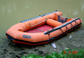
4. INFLATABLE RUBBERIZED BOATS
S/No Specification
1 SCOPE: This specification relates to the detailed requirements for the design,
construction, tests & trials, documentation and warranty of 4.5m
Inflatable Boats, intended for NDRF.
2 Functions
3 Design 1.
4 Features
The inflatable boat shall perform the following tasks:
(a) Search & Rescue during floods
(b) Transport men and material
(c) Support boat for body search and diving.
The boat shall be designed to be seaworthy/River worthy
/Stationary water bodies/ Stagnated water to carry out functions
listed under head function with full complement and at speeds (not
less than 10 knots commensurate with a range of 25HP to 40HP
OBM).
ii.
iii.
iv.
The craft shall be stable and should meet swamp & stability
requirement specified at Para 18.16 of this Specification.
The boat shall be designed to have good manoeuvrability and
throttle response throughout its speed range (using 25HP to 40HP
OBM 4 stroke) and particularly when operating at flowing water
speed speed of 10-15 Knots.
High-pressure inflatable keel for better performance handling.
and
v. V-shaped hull for improved stability and handling in rough
waters.
vi. Minimum 5 air chambers for safety and redundancy
i. Grab lines for easy boarding and disembarking
ii. D-rings for attaching equipment and accessories
iii. Self-bailing drain valve for easy water evacuation
iv. Compatible with OBM range of 25 to 40 HP
5 Principal
particulars
(a) Length exterior
(b) Breadth exterior
(c) Length interior
(d) Breadth interior
6 Built 1)
Not less than 4500 mm
Not less than 1960 mm
min. 3200 mm
- min. 1000 mm
(e) Dia of Buoyancy Tube Not less than 480 mm
(f) Carrying Capacity
(g)Weight of the craft
10 men (82.5 Kg per person)
Not more than 90 kg for boat &
Not more than 40 Kg for the floor
boat & accessories (Without
OBM)
The craft shall be built of Buoyancy Tube made of Composite
Fabric consisting of Hypalon (outer layers) and Neoprene (inner layers) of 1670 Dtex or equivalent, inspected by IRS as per ISO 15372.
2) The bottom floor of the boat shall be made of the same fabric as
buoyancy tube.
3) Reinforcement of the boat shall be provided using rubberized strips
of Hypalon (outer layer) and Neoprene fabric (inner layer).
4) The stern of the boat formed by a transom shall be made of
Rry Page 7 of 18
7
S/No Specification
Approval And
Inspection by
Inspection
Authority
1)
2)
Marine Plywood or Foam Core with fiberglass three layers
which OBM can be mounted
n
The Craft is to be constructed under the approval of Indian
Register of Shipping (IRS) in accordance with ISO 6185, Part 3
(2014) and the minimum requirements specified in
specification.
this
Parameters not mentioned in this specification would be in
accordance with ISO 6185, Part 3 for inflatable crafts, so as to
ensure that the craft meets all functional/material requirement
specified in this specification. Class approval shall cover
following aspects: -
(a) Design vetting
(b) Drawing approval
(c) Material Inspection
8 Certification
9 Construction
Details
(d) In-process Inspections
(e) Tests & Trials in flowing water and rescue simulation
per committee
as
Indian Registrar of Shipping (IR Class) to ensure that it meets
safety standards
1)
2)
3)
4)
Buoyancy Tube: The material used for buoyancy tube shall be of
Hypalon (outer layers) and Neoprene (inner layers) composite
fabric, of 1670 Dtex or equivalent inspected by IRS as per ISO
15372
The Buoyancy Tube shall be divided in to a minimum of 05 air
tight compartments by means of baffles/bulk-heads. Each
compartment shail be fitted with a combined inflation/deflation
valve.
The valves shall be made of rubber moulding and plastic nylon
material or alternate marine grade material approved by class.
The valves should be of reputed make and approved by
Classification society for use on inflatable crafts.
The ends of the tube shall be conical and should terminate in
suitably stiffened rubber conical flat ends to take impact loads
during coming alongside/lowering.
5) The two legs of the Buoyancy Tube shall be parallel and the
width readings at the transom and at midship shall not differ by
more than 3%.
6)
7)
8)
9)
The tube shall be strong enough to sustain the effects of ramming
whilst coming alongside at the speed of 05 knots.
The upper layer shall be strong enough to bear the rubbing
impact against rough surfaces. In addition, an emergency repair
kit with quick drying adhesive and ready use repair patches shall
be provided.
The construction of the Buoyancy Tubes should be in accordance
with class approved drawings and production processes.
The attachment of bulkheads in the buoyancy tube shall be such
that each chamber is rendered air tight under specified pressure.
10) The seams in the buoyancy chambers shall have an overlap not
less than 3cm width and should be pasted with cold glue
vulcanisation process or equivalent Class approved process.
11) An additional strip is to be glued at the edge of each panel
junction as well as strip inside all assembled parts in order to
Page 8 of 18
S/No Specification
ensure a perfect water tight preventing from any leakage.
Inflation/Deflation Valve
1) The Inflation/Deflation valve shall combine a high-pressure air
connection with a deflation valve in each air tight chamber and
shall be as per ISO 6185-3 (2014).
2) The valve shall be fitted proud of the buoyancy tube on inner
side of the buoyancy tube to enable identification/location in
darkness.
3) The material of inflation/deflation valve fitted on the buoyancy
tube shall be of suitable material for marine application.
4) Alternate design/arrangement for inflation/deflation valves which
meet the above functional requirements is acceptable subject to
the approval of Classification Society.
Floor
1)
2)
3)
4)
5)
The floor shall be made of Hypalon (outer layers) and Neoprene
(inner layers) composite fabric, of 1670 Dtex or equivalent
inspected by IRS as per ISO 15372.
The floor shall be bonded to the underside of the buoyancy tube
and attached by a floor retaining strip to the transom board.
It shall be strengthened on its underside in way of the keelson by
a keelson chafing strip of minimum 100mm wide fabric.
Chafing strips shall also be bonded to the underside at the after
ends of the tubes.
Special attention shall be paid to the attachment of the floor to
the buoyancy tube to ensure that the resulting joint is water tight.
6) Special care is also to be taken that the floor is perfectly taut and
smooth and has no puckers, when the craft is assembled and
ready for use.
Self-Bailers/Drain Valves
1)
2)
3)
Two self-bailers akin to NRV shall be located on the lowermost
part of the transom board near the rear end fitment of the keel
close to the centre line.
The same shall be provided with a flexible flap to overcome
pressure on the NRV in following seas.
The self-bailers shall automatically remove water from the craft
at higher speeds.
4) Additional Scupper should also be fitted to Transom.
Transom
1) The transom board shall be fitted and securely bonded to the
buoyancy tube and the floor so as to provide a water tight joint.
2) The Transom shall be designed for use with 25 to 40 HP ОBM
3) The transom shall be made of marine plywood or foam core
coated with 03 layers of 6 mm FRP/GRP of appropriate
thickness and to be suitably fitted out with engine mount made of
marine grade Aluminium alloy plate and chafing patch.
4) Hypalon coated fabric shall be pasted on the surface area of the
R
Page 9 of 18
S/No Specification
transom to prevent it from damage as well as loosening from e
tube body. Separate strip of suitable size shall be provided on the
bottom of the transom to minimize chance of damage.
5) Details regarding craft identification No. etc. shall be engraved
on a builder's plate fitted on the inner side of the transom on
starboard side. Towing rings, cleat and 'U bracket shall be
provided as per approved drawing.
Floor Boards.
1) The boat is desirable to be without floor boards. Inflatable and
other designs promoting speed of /in deployment or other
benefits will be welcomed.
2) However, if the floor beds are to be made in that case it should
be: 1) The Floor boards shall be made of High Strength
Tempered Anodised marine grade Aluminium alloy with a foam
mat (non-skid) finish.
3) These boards (Four/Five pieces) shall be interconnected together
to form a rigid platform. The forward/bow piece of floorboard
may be made of marine plywood (IS 710) coated with FRP
lamination.
Keel
1) The boat shall be provided with inflatable keel of suitable size
provide the rigidity & stability during operation of boat.
Stowage Pockets.
1)
2)
3)
to
Minimum two Stowage pockets shall be attached to the buoyancy
tube in the forward in board side.
The stowage pockets provided shall be capable of holding
dynamic weight of 6 Kgs.
Holes are to be provided at the bottom of the pocket to drain
water (Size 340mm x 280mm x 90mm).
Rubbing Strips..
1) Following single piece Rubbing Strips of moulded neoprene rubber
of 2" width (where not mentioned) and extending along the entire
length shall be attached to the buoyancy tube for the protection
the craft: -
(a) Bow rubbing strip 4".
(b) Outer anti chafing strip 100mm wide on both sides.
(c) Anti-Chafing Strip under Keel of V shape.
(d) Two Beaching Strips 100 mm wide under buoyancy
tubes
(e) Chafing patch for coxswain's position
Carrying Handles.
1) Minimum seven Carrying handles shall be provided, three on each
side and one front lifting handle.
2) The handles shall be suitably reinforced to take a weight of 300
kgs all together.
3) The handles shall be of Moulded Neoprene Rubber bonded to the
buoyancy tubes.
L
Page 10 of 18
S/No
10 Material
specifications
Specification
Towing Fittings and Securing Arrangements.
1) Following Towing fittings shall be provided. Towing fittings
shall consist of suitably sized D Shackle of SS AISI 316(to pass
towing rope) securely attached to fabric reinforcing patches
bonded to the buoyancy tube.
a
b
Towing/ Lifting fittings, forward - One on either side of the
craft, below the buoyancy tube at the beginning forward
curve in the buoyancy tube.
Towing fittings, aft - One on either side on the transom,
shall be used if craft is employed for towing purposes.
c Load Test. The towing arrangement shall be load tested
per ISO 6185-3.
Oars & Oar Securing Assemblies.
as
Two nos. of oars to be provided. Oars shall be positioned parallel/30° to
the vertical when secured inside the inboard side of buoyancy tubes.
Adequate securing arrangement shall be provided so that the oars are
intact.
The buoyancy must have fittings for fixing oars.
1)
2)
3)
4)
Foot Bellow pumps
Heavy duty bellow type foot pump (reputed make) of suitable design
shall be provided to inflate the craft in approximately 20 minutes.
The housing of pump is to be made of a heavy duty yet light weight
marine composite.
The Bellow to be made of coated reinforced fabric and all metal parts
should be of stainless steel.
In addition, one heavy duty electric inflation pump of reputed make
(12 V DC) and one pressure guage (capable of measuring pressure of
tubes) of reputed make to be provided.
Fabric Fittings:-Patches, doublers, anchorages, etc. shall be made
and positioned as shown on the drawing which indicates finished size.
Suitable tape/webbing reinforcement shall be used to distribute stresses
adequately.
Grab line
There shall be grab line nylon braided (as per IS 4227) of dia. min.
12.0mm all along the sides for safety to be provided.
1) Material Specification for the various items to be used for
construction of Inflatable crafts are as follows: -
a
b.
C.
d.
Tube Fabric: Hypalon or PVC
Floor (not Hull) Material: Fiberglass or Aluminium, 3-piece
detachable plates with single running channel on each side or
new design to be submitted if any
Transom plate: Fiberglass with Stainless steel plates. /OBM
SADDLE.
The Material Specification for buoyancy tube, inflatable keel
composite fabric of 1670 Dtex or equivalent as per ISO 15372
and inspected by IRS.
e. The Material Specification for floor system as per recognized
Page 11 of 18
S/No
f.
Specification
national/international standard.
The material specified shall be strictly adhered to and o
deviation is permitted. Materials referred to as approved shall
be so approved by the Classification Society in accordance
with the requirement specified in this Rule.
g. The colour of all exposed surfaces / material shall be highly
visible orange color.
Adhesive
1)
2)
The adhesive shall be Neoprene based contact adhesive of good
quality and to be suitable for service in tropical environments
as per specification.
The adhesive shall consist of a dispersion of polychloroprene in
a low boiling point solvent and may have additions of resins to
promote building tack.
3) The adhesive shall consist of 2 components, Part 1 and Part 2,
Part I being the basic neoprene dispersion and part 2, the
accelerator (hardener).
4) The adhesive should be approved by Classification Society for
use on inflatable and meeting the minimum requirements
specified in ISO 6185-3 (2014).
5) Alternate adhesive superior in properties are also acceptabie
subject to type approval of Classification Society as per ISO
6185-3(2014).
The principal components of the complete assembly are as follows: -
Huil
Buoyancy tube - Divided in minimum 05 compartments and
complete with rubber conical flat ends.
11 Principal
components of
boat 1)
L
2) Bulkheads -Dividing the buoyancy tube into min
compartments.
5
3) Inflation/deflation valves - one set per chamber.
4) Transom- fitted with engine mount, anti-chaff patch.
5) Floor - in proofed fabric
6) Keelson chafing strip - 1 No.
7 Aft chaffing strip -1 No.
8) Inflatable Keel- 1 No.
Hull Fittings
1) Bow Rubbing strip- 1 No.
2) Side Rubbing strip Aft -1 set
3) Carrying Handles (Patch rubber with handle)- 4 Nos
4) Grab line - 1 set
5) SS to AISI - 316 Hook on transom - 2 Nos
6) SS to AISI - 316 "D" rings - 2 Nos
7) Pockets for stowage- 1 Nos (One for wireless set & one for
inflation below pump)
8) Oars (Shall be light weight not more than 4Kgs and positively
buoyant in water)
9) Repair Kit (small) - fabric patches 05, adhesive tube (Dendrite)
500 gm, roughing tool, spanners of required sizes, yamadur (hardener)
Valises and Store bags
Rn Page 12 of 18
S/NO Specification
1) Heavy duty storage bag for Hull - 01 No.
2) Storage bag for oars & other accessories - 01 No
Additional Spares
(i) Inflation/Deflation Valves 10 Nos
(ii) Pressure gauge 01 Nos
(iii) Plugs for Water Drain- 04 Nos
(iv) NRV for Water Drain - 10 Nos
(v) Electric Inflation pump 01 No
(vi) Bellow Inflation Foot Pump 02 Nos
12 Accessories
13 Production.
14 Records
(vii) Patching material with adhesive to repair leak/damage in
buoyancy tube.
(viii) Scuppes for bailing water from Transom.
i. Inflatable foot pump
ii. Repair kit
iii. 06 Oars
iv. Carry bag or storage cover
v. Cordless Blower
vi. Puncture Kit
Manufacturing of the craft should be as per the detailed drawings
approved by Indian Register of Shipping (IRS) and meeting the
requirements mentioned in this specification. The production processes
should also be approved and supervised by the IRS.
Tolerance
1) General tolerances on all dimensions shall be ±1.5 % unless
otherwise specified in this specification or approved by
Classification Society. The exceptions to this general limit shall
be in respect of stuck-on components length of webbing and
cordage, and the overall dimensions of components etc; these
items shall be given a sliding scale tolerance which increases in
accordance with the magnitude of dimensions.
Production Damages
1) Any Production damage irrespective of size shall be repaired by
complete part / panel replacement only. The replacement is to
undertaken by the contractor free of charge at the consignee place
as soon as possible and in any case not later than one month from
the date of receipt of intimation.
2) No patch repair is permitted on buoyancy tube/ floor. In case of
production damages only part/ Panel Replacement shail be
permitted.
3)
i.
ii.
Where a part panel replacement is necessary, the following
parameters shall apply:
On the buoyancy tubes, not more than one part panel
replacement will be permitted on each craft.
On the floor not more than one part panel replacement will
permitted on each craft
be
1) The builder shall develop and maintain records that demonstrate
the effective operation of his quality control system and shall
make these records available for review of the Inspecting agency.
2) Inspection records shall include explicit identification of the
material, part sub-assembly, equipment, sub-system or system,
dy Page 13 of 18